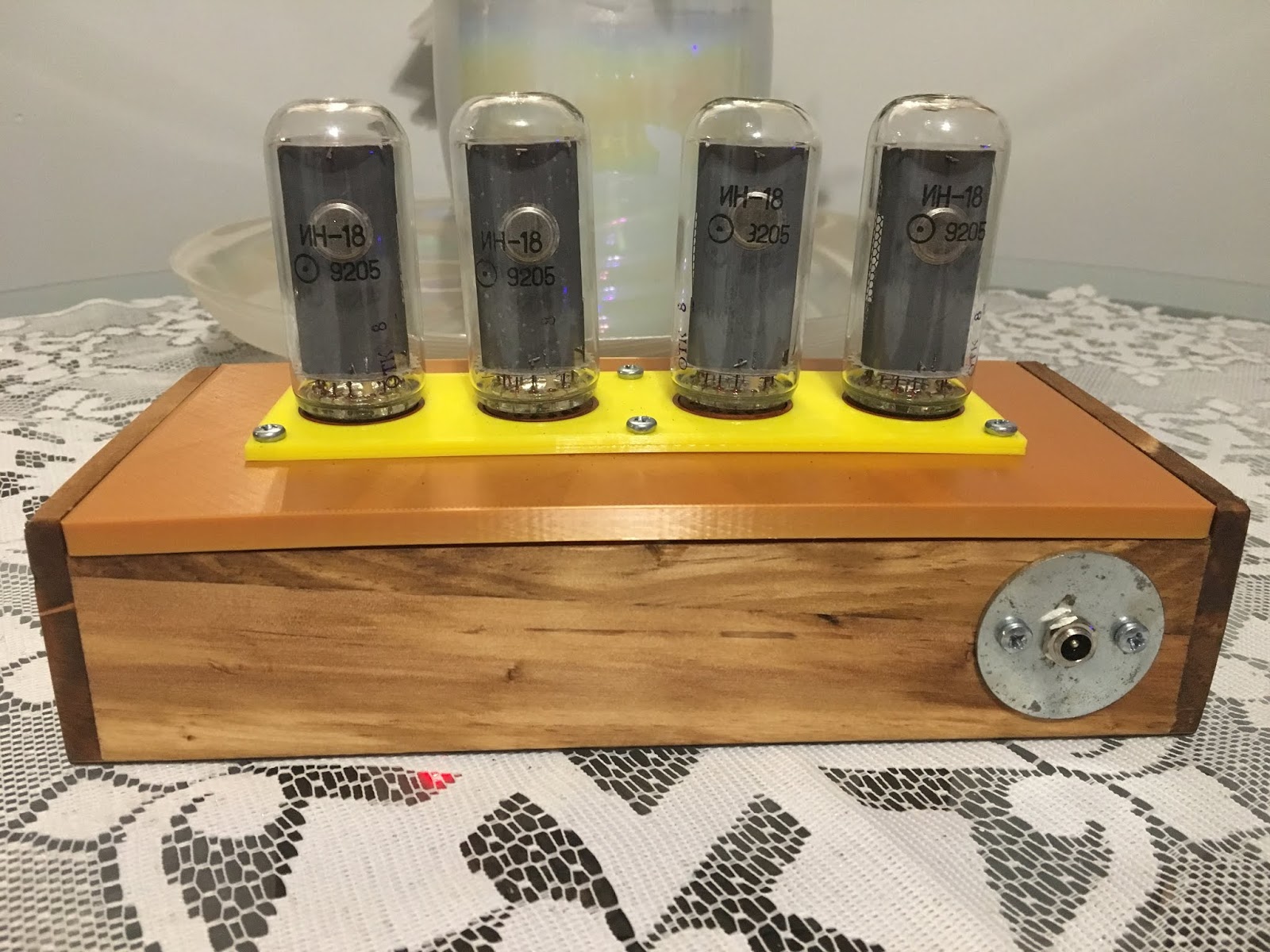
I've always wanted to tinker around with some nixie tubes. I acquired some IN-18 tubes about 15 years ago, and just kind of ignored them. I have finally started tinkering with them.
The first thing I needed to do before I could even do anything with the Nixie Tubes, is build a power supply that is capable of driving them.
I utilized DIYLC (Do it Yourself Layout Creator) to design the layout of the strip-board.
Circuit Layout designed with DIYLC:

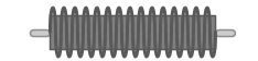
DIYLC was missing an Axial Lead Inductor on it's component palette. I ended up using Java to create my own component.
Inductor I Added:
This is my first circuit built on strip-board. I am a tad messy, hence the reason why I am opting for Strip-Board instead of etching a PCB. You can see where I accidentally laid it on my hot iron. I made a few placement mistakes and and I did not feel like unsoldering, so I utilized DYLC to move some of the components around to accommodate my mistakes.
Circuit built on Strip-Board:

Finally, I was able to load test the circuit, to make sure that it would drive four nixies.
Load Testing Circuit:

I'm pretty clumsy, so I designed a tube socket holder for the nixie tubes:
- Thingiverse IN-18 Nixie Tube PL31p Socket Mounts
Holder:

I also mounted everything to a board, while tinkering, because of the very same reason.
Wood Board:

Video:
Logic:
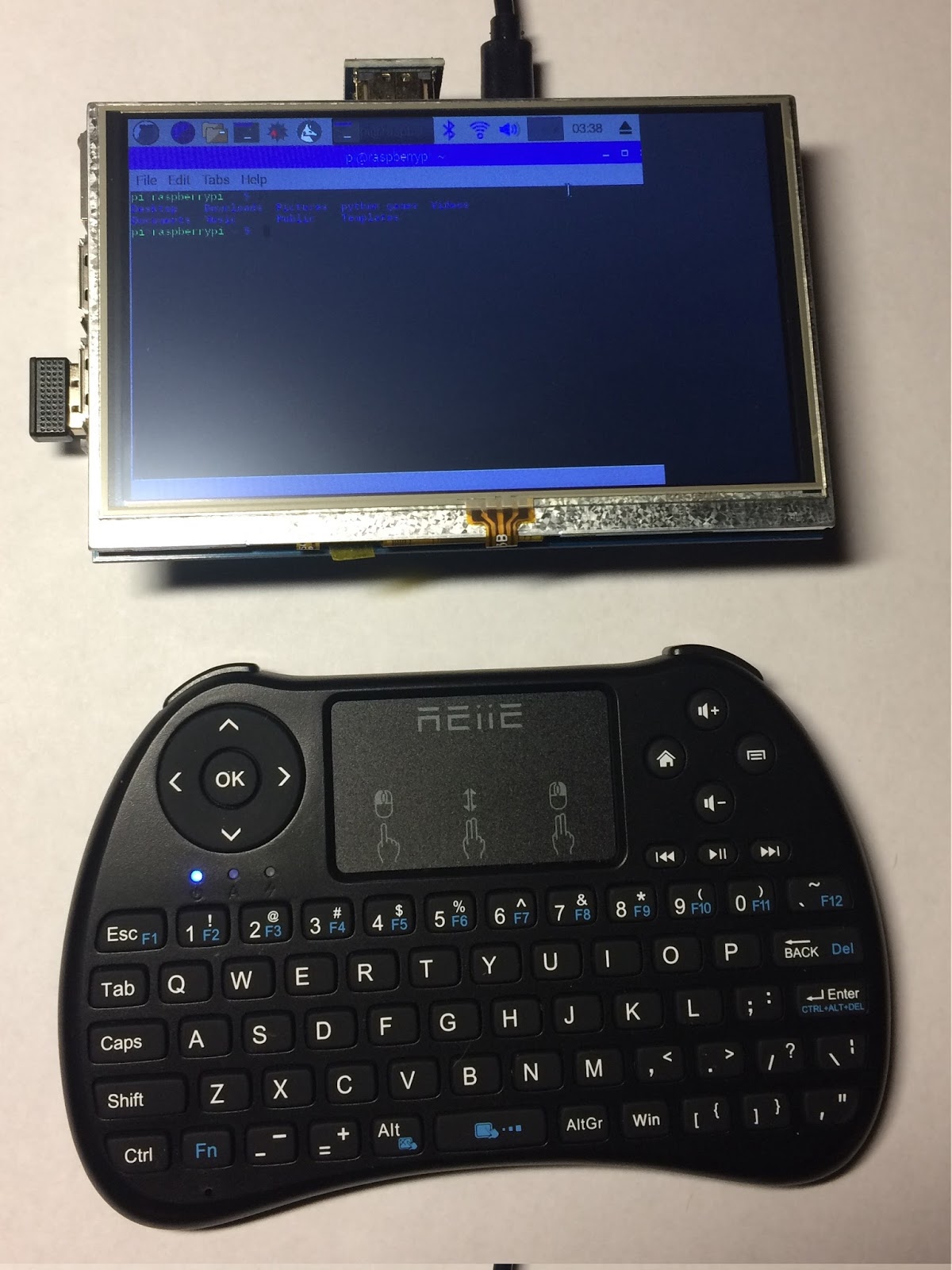
I am utilizing an Adafruit HUZZAH ESP8266 Breakout board to control what is displayed on the tubes.
https://github.com/jefferoonie/ESP-Huzzah-Nixie-Tube-Clock
ESP8266 → MCP23017 → K155ID1
Breadboard rats-nest to PCB:
Decided to have a PCB made, so that I could get rid of the rats nest that is hanging out on that breadboard.
Drew Schematic:

Routes:

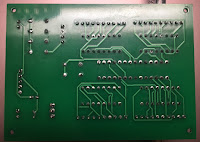
Blank PCB Arrived:


Populated PCB:

There are many things that I would have done differently like:
- Better labeling and marking of polarity, and etc.
- Bigger screw holes.
- Maybe flipped two of the BCD chips.
Finished:
Ended up making the finished housing out of a wood box from Hobby Lobby.
Drew up, and printed a top of the box, based on my previous tube socket holder:
IN-18 Nixie Tube PL31p Socket Mounts - Hobby Lobby Box Lid


Update: Webserer Controls
Decided to throw a web-server on it, for changing time zones, and daylight savings. It captures the offset that correlates with the time zone, and puts it into the emulated EEPROM. The code in Github has been updated to reflect this
Ugly, but works for me.